Monitoring and safety
A strainer element does not report its condition by itself. The differential pressure between inlet and outlet is the only reliable indication of how far it is clogged. We configure the measurement the way your plant needs it – from a differential pressure gauge read on site to a signal in the control room.
0–160 mbar to 0–16 bar
10, 16 or 25 bar
Switch contact or 4–20 mA
IP 33 to IP 65
A strainer element does not lose its effectiveness suddenly, but gradually. As it becomes loaded, the resistance that the medium has to overcome increases – and with it the pressure difference between strainer inlet and outlet. This difference can be measured long before flow rate or plant output drop noticeably.
Cleaning too early costs downtime and staff time. Cleaning too late lets the pressure loss across the strainer rise further, the pump works against the resistance and, in the worst case, the strainer element is mechanically deformed. Differential pressure turns the cleaning interval into a measured value instead of an estimate.
As measuring instruments we fit WIKA products. The series with microswitch and with output signal cover the range from a pure display to connection to the control system. If another make is standard in your plant, we fit that as well. For a customer-supplied instrument we provide the matching connections.
The levels build on one another. Which one fits depends on whether someone regularly walks past the strainer – or whether the alarm has to reach the control room.

The housing is given two sockets upstream and downstream of the element, usually 1/4 or 1/2 inch. Measurements are taken with a portable instrument when needed, and the gauge can be retrofitted at any time. This is the most economical option if monitoring is to follow later.

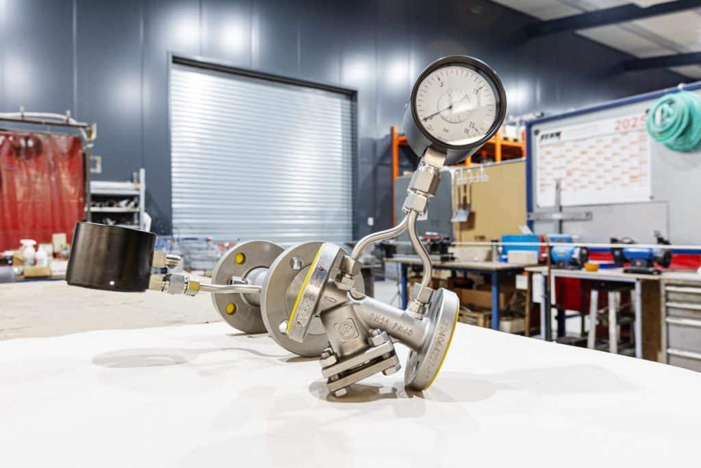
A differential pressure gauge with Bourdon tube, piped to the housing via two parallel connection stems. Dial size 100 mm, accuracy class 1.6, display ranges 0–6 or 0–16 bar, dual scale in bar and metres of water column on request.

In addition to the display, a microswitch that switches at the set limit value – single or double, for example for pre-alarm and shutdown. Switching hysteresis max. 5 percent of full scale, connection via cable socket or angular connector.

The differential pressure is output continuously as a current signal, in 2-wire technology. This allows the trend to be recorded: the control system detects not only the limit value but also how quickly the strainer is clogging.

On request the same instrument shows the operating pressure of the plant in addition to the difference – designed for 10, 16 or 25 bar. This saves a second pressure gauge and an additional measuring point.

Analogue or digital thermometers, pressure transmitters and sight glasses can be fitted to the same housing. The connection nozzles are positioned in the design where you will be able to read them later.
Differential pressure gauges and other measuring instruments can be combined individually with any strainer type.
The values describe the instruments we usually fit. Other measuring ranges, materials and approvals are possible.
| Feature | Value | Note |
|---|---|---|
| Measurement | ||
| Make | WIKA | other make or customer-supplied instrument possible |
| Differential pressure display range | 0–160 mbar … 0–16 bar | selected according to design |
| Accuracy class | 1.6 or 2.5 | depending on version |
| Dial size | 100 mm | easy to read from a distance |
| Operating pressure display | 10 · 16 · 25 bar | optional in the same instrument |
| Operating limits | ||
| Permissible differential pressure across the strainer | max. 2 bar | limit of the housing, not of the display |
| Recommended operating value | max. 0.5 bar | above this, clean the element or increase the area |
| Medium temperature | −10 … +90 °C | at the instrument, not at the strainer |
| Ambient temperature | −10 … +70 °C | — |
| Ingress protection | IP 33 to IP 65 | IP 65 for contact and signal instruments |
| Separating diaphragm and seals | FPM / FKM | other materials on request |
| Connection and signal | ||
| Process connection | 2 × G 1/4 female | or parallel connection stems G 1/2 |
| Measuring sockets on the housing | 1/4" or 1/2" | can also be prepared without instrument |
| Switch contact | Microswitch, single or double | switch point adjustable |
| Version with contact | DELTA-comb | with integrated operating pressure display |
| Version with signal | DELTA-trans | output signal 4–20 mA |
| Switching hysteresis | max. 5 % of full scale | — |
| Output signal | 4–20 mA, 2-wire | for the process control system |
| Electrical connection | Cable socket · angular connector 6-pin + PE | also fixed cable |
We set the limit value for your plant; it results from the strainer, the medium and the pump. The reference point is the pressure loss in the clean condition, which we calculate during the design. The switch point lies above it – with enough margin that normal fluctuations do not trigger an alarm. At the same time it remains well below the pressure at which the element is mechanically stressed. It can be adjusted on the instrument at any time, as soon as operation shows the limit in practice.
Yes. Before production starts you receive the design drawing for approval – the drawing also shows the position of the measuring nozzles and the monitoring version. Only once you have confirmed it does the order go into production.
Certainly. Drawings, specifications, parts lists or the data sheet of the previous strainer are the best basis. Our design engineers adopt your requirements and adapt them where manufacturing or the applicable code requires it – we agree any deviations with you beforehand.
Yes, provided the housing has the two measuring sockets. That is why it is worth providing them straight away, even if no instrument is fitted at first – otherwise welding on the pressure housing would be necessary later.
It depends on the calculated pressure loss in the clean condition: the range should resolve this value and the planned switch point clearly. A range that is too large makes small changes invisible. We propose the range together with the design.
The switch contact reports an event: limit value reached, yes or no. The 4–20 mA output signal transmits the measured value continuously – so the control room can also see how quickly the differential pressure is rising and can schedule cleaning instead of waiting for the alarm.
No. There are versions with an integrated operating pressure display, designed for 10, 16 or 25 bar. One instrument, one measuring point, two values.
Yes. Instruments with the appropriate certificates are available for safety-related applications and for offshore use. Tell us the required approval with your enquiry, as it influences the choice of instrument.
WIKA instruments are standard: the series with microswitch for the switch contact and the series with output signal for 4–20 mA. If another make is specified in your plant, we fit it or provide the matching connections for a customer-supplied instrument.
All topics at a glance: Strainer options
Tell us whether someone walks past the strainer or whether the alarm has to reach the control room – this determines the level of equipment. We need the flow rate, medium and mesh size for the pressure loss in the clean condition.