Spectacle blind · Reversible line blind
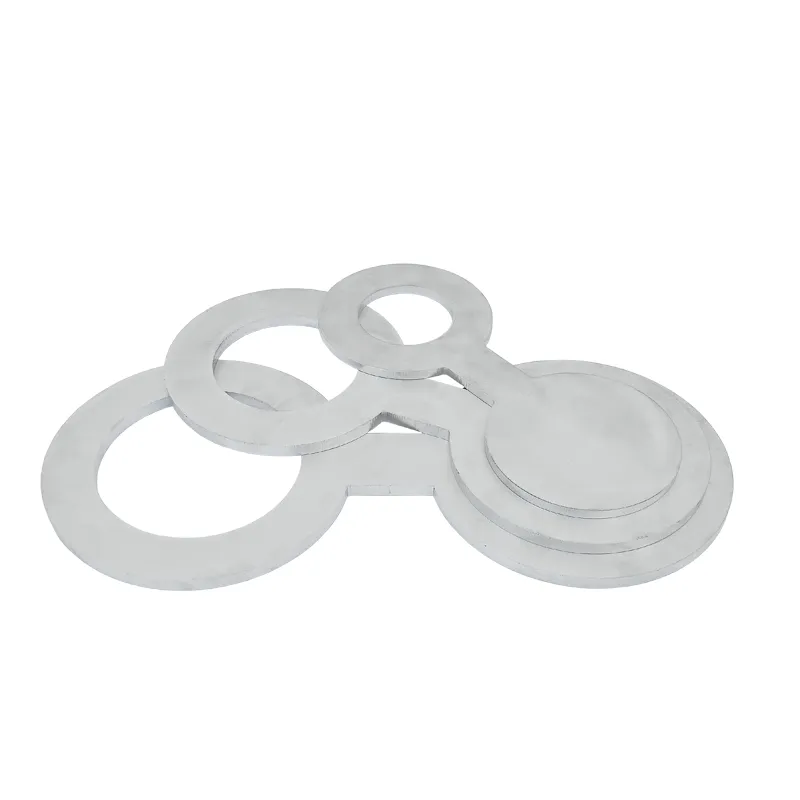
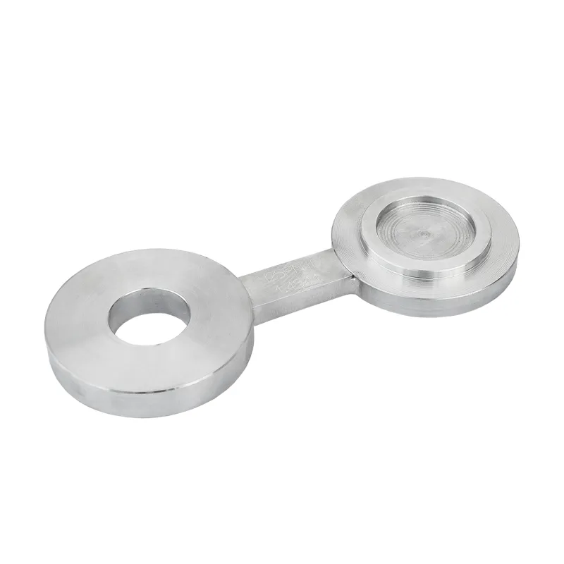
The spectacle blind, also known as a figure 8 blind, combines a spade blind and a paddle spacer in one piece, joined like a pair of spectacles. Loosen the bolts, reverse the blind, tighten again – the line is closed or open, depending on which half sits in the joint.
The advantage over two separate plates: nothing can be mislaid, and the state of the line can always be read from the outside.
The two positions
The spectacle blind has two halves. Which one sits in the flanged joint determines the state of the line – the other hangs visibly beside it.
Solid half inserted
The solid plate isolates mechanically. The open ring protrudes and shows: closed here. No doubt, no mix-up, no need to consult the flow diagram.
Open half inserted
The ring with full bore sits in the joint, the solid plate hangs outside. The installed length stays the same – bolts and gaskets are the same as before.
Because both halves have the same thickness, nothing changes at the flanged joint when the blind is reversed. That is the real gain over two separate plates.
Function and advantage
Once installed, the spectacle blind sits between two flanges of the pipeline. One half sits in the joint, the other stands outside next to it. To change over, you loosen the bolts, reverse the blind and tighten them again.
The spectacle blind pays off wherever a line is regularly isolated and released again. If the line is blinded only once, a spade blind is sufficient.

Pivoting spectacle blind
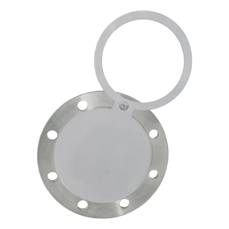
From medium nominal sizes upwards, a spectacle blind becomes heavy – at DN300 and PN40 the solid half is 35 mm thick. Removing it completely for reversing is then no longer a quick job.
This is what the pivoting spectacle blind is for: a design with a bore that pivots on one bolt of the flanged joint. The blind stays on the flange and is only swung round.
Whether a pivoting spectacle blind makes sense depends on two points: how often the blind is reversed and the space next to the flange.
Design
Material
The spectacle blind stays permanently between the flanges. One half is in the medium, the other hangs outside in the air. The material must therefore suit both.
Standard
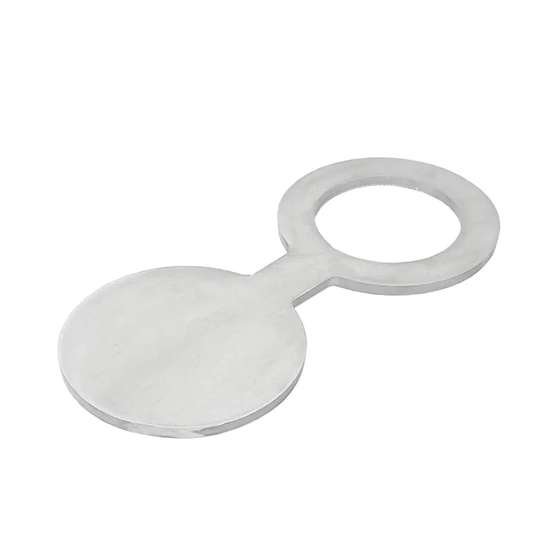
This stainless chromium-nickel steel needs no coating. It stays bright in water, in many aqueous solutions and in humid air. The plate therefore does not seize in the flange, and the handle remains legible.
Economical alternative
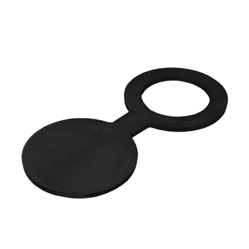
The heat-resistant pressure vessel steel P265GH is designed for pressure and elevated temperature. It suits lines in unalloyed steel, as are usual for steam, hot water, oil and gas. Where moisture and oxygen come together, it rusts. In dry or oily media this does not matter.
Other materials are available on request, for example 1.4571 for media containing chlorides. Tell us the medium, the temperature and the material of the flanges. We will then recommend the right design.
Vent
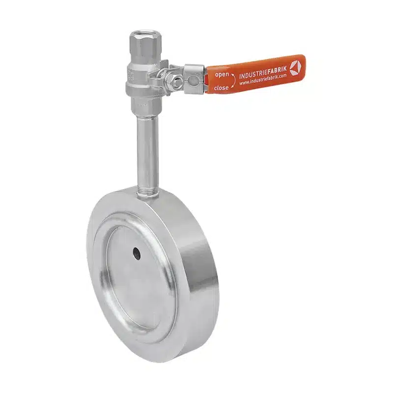
Medium often remains trapped behind the closed half of the spectacle blind. Sometimes there is still pressure there as well. For this, the spectacle blind with vent has a connection on the side of the blind half. Through it you release pressure and medium in a controlled way before the bolts are loosened.
Standard
The ball valve sits on the outside of the blind half. A bore connects it to the isolated section of the line. Before reversing, you depressurise and drain the section through it. When refilling, the air escapes.
With flange connection
Instead of the ball valve, the blind half has a flanged nozzle. You connect your own valve, a drain line or a pressure gauge to it. The isolation point thus also becomes a connection point for draining and pressure testing.
The connection on the blind half depends on your plant. Whether flange connection, weld connection, female thread or male thread: we fit the connection type that suits your line. We supply the accessories to your specification.
Tell us nominal size, pressure rating and medium. Also tell us which connection type and which accessories you need. If the spectacle blind is made as a pivoting spectacle blind, we position the connection so that it stays clear when swung round.
Sealing face
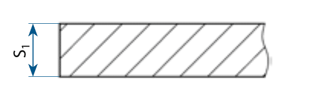
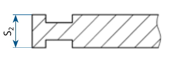
A line blind must match the sealing face of the flanges between which it sits. As standard it is flat on both sides. For flanges with tongue or groove to DIN EN 1092-1 we make the mating form. If the flange has a tongue, the plate has a groove on that side – and vice versa.
Flat · Standard
Flat and unmachined on both sides, optionally with raised face Form BB. Suits flanges with a flat sealing face or a raised face.
Groove – groove
A groove on both sides. The plate sits between two flanges with a tongue.

Groove – tongue
One side with a groove, the other with a tongue. This is the form for the usual tongue and groove joint between a tongue flange and a groove flange.

Tongue – tongue
A tongue on both sides. The plate sits between two flanges with a groove.
When reversing, the spectacle blind needs more travel. Tongue and groove must first come fully out of engagement before the blind can be turned. For this, the flanges are spread further apart than with flat sealing faces.
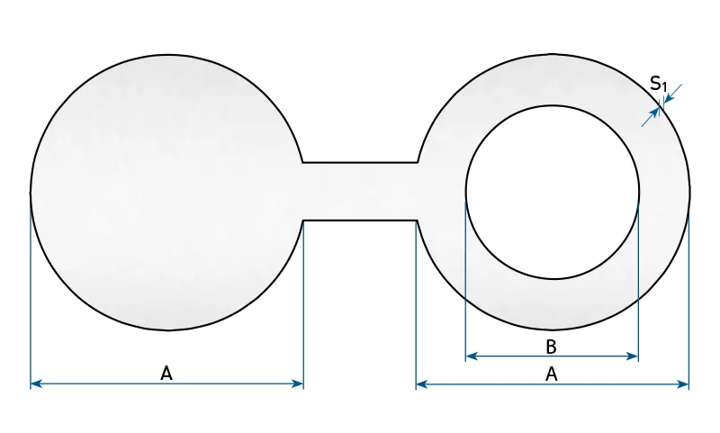
The dimension table gives the thickness S1 of the flat design. With tongue or groove we determine the thickness separately and state it in our quotation.
Tell us the sealing faces of your flanges, for example Form C and Form D to DIN EN 1092-1. We will then supply the matching mating form.
Dimensions
∅ A is the outside diameter of both halves, ∅ B the free bore of the open half, S the thickness. All dimensions in millimetres.
| DN | ∅B | PN6 ∅A/S | PN10 ∅A/S | PN16 ∅A/S | PN25 ∅A/S | PN40 ∅A/S |
|---|---|---|---|---|---|---|
| DN10 | 16 | 39 / 4 | 46 / 6 | 46 / 6 | 46 / 6 | 46 / 6 |
| DN15 | 20 | 44 / 4 | 51 / 6 | 51 / 6 | 51 / 6 | 51 / 6 |
| DN20 | 25 | 54 / 4 | 61 / 6 | 61 / 6 | 61 / 6 | 61 / 6 |
| DN25 | 31 | 64 / 4 | 71 / 6 | 71 / 6 | 71 / 6 | 71 / 6 |
| DN32 | 40 | 76 / 4 | 82 / 8 | 82 / 8 | 82 / 8 | 82 / 8 |
| DN40 | 46 | 86 / 4 | 92 / 8 | 92 / 8 | 92 / 8 | 92 / 8 |
| DN50 | 58 | 96 / 6 | 107 / 10 | 107 / 10 | 107 / 10 | 107 / 10 |
| DN65 | 74 | 116 / 6 | 127 / 10 | 127 / 10 | 127 / 10 | 127 / 10 |
| DN80 | 86 | 132 / 6 | 142 / 12 | 142 / 12 | 142 / 12 | 142 / 12 |
| DN100 | 110 | 152 / 6 | 162 / 10 | 162 / 10 | 168 / 15 | 168 / 15 |
| DN125 | 136 | 182 / 8 | 192 / 10 | 192 / 10 | 194 / 15 | 194 / 15 |
| DN150 | 164 | 207 / 8 | 218 / 12 | 218 / 12 | 224 / 20 | 224 / 20 |
| DN200 | 215 | 262 / 10 | 273 / 12 | 273 / 15 | 284 / 20 | 290 / 25 |
| DN250 | 268 | 317 / 12 | 328 / 15 | 329 / 20 | 340 / 25 | 352 / 30 |
| DN300 | 319 | 373 / 12 | 378 / 20 | 384 / 20 | 400 / 25 | 417 / 35 |
| DN350 | 351 | 423 / 15 | 438 / 20 | 444 / 25 | 457 / 30 | 474 / 35 |
| DN400 | 402 | 473 / 20 | 489 / 20 | 495 / 25 | 514 / 30 | 546 / 40 |
| DN450 | 453 | 528 / 20 | 539 / 25 | 555 / 30 | 564 / 35 | 571 / 45 |
| DN500 | 503 | 578 / 20 | 594 / 25 | 617 / 30 | 624 / 40 | 628 / 50 |
The dimensions apply to each half – the complete blind including the web is correspondingly longer. Higher pressure ratings up to PN160 and larger nominal sizes are available on request.
Enquiry
For a quotation we need nominal size, pressure rating and material. If the blind is reversed frequently or there is little space next to the flange, select the pivoting spectacle blind. Add further sizes with “+ further item”.
In the shop
For standard sizes the shop is the quicker route. You select nominal size, pressure rating and material and add the blind directly to the basket.
To the spectacle blind in the shop →
Direct
+49 34956 39960
Monday to Friday, 7 am to 4 pm (CET)
You can reach us by email at info@industriefabrik.com.
Frequently asked questions
The spectacle blind pays off when the line is regularly switched between closed and open: it stays at the joint, nothing can be mislaid, and the state can be read. If the line is blinded only once, a separate spade blind and paddle spacer are sufficient.
That depends on nominal size and pressure rating – at DN300 and PN40 it is two plates, each 35 mm thick, plus the web. From this size upwards the pivoting spectacle blind is the more practical design.
A spectacle blind with a bore that pivots on one bolt of the flanged joint. For reversing, the bolts are loosened and the blind is swung round instead of being removed.
Yes. Both halves have the same thickness – bolts, gasket seating and face-to-face length do not change. That is exactly why the spectacle blind is the safe choice for frequent changes.
The dimensions follow DIN 2626; installation is between standard flanges to DIN EN 1092-1 or ANSI B 16.5. As standard, the sealing face is Form AA, unmachined.
For a quotation we need nominal size, pressure rating and material. Also tell us how often the blind is reversed and how much space there is next to the flange – this decides whether a pivoting spectacle blind makes sense.