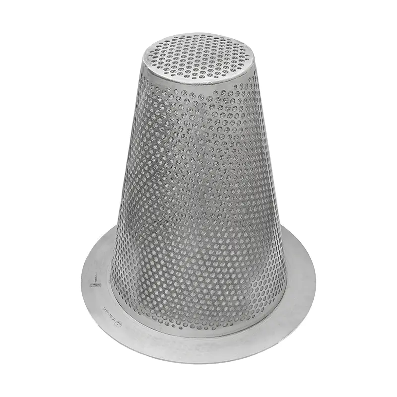
Witch hat strainer · Temporary strainer
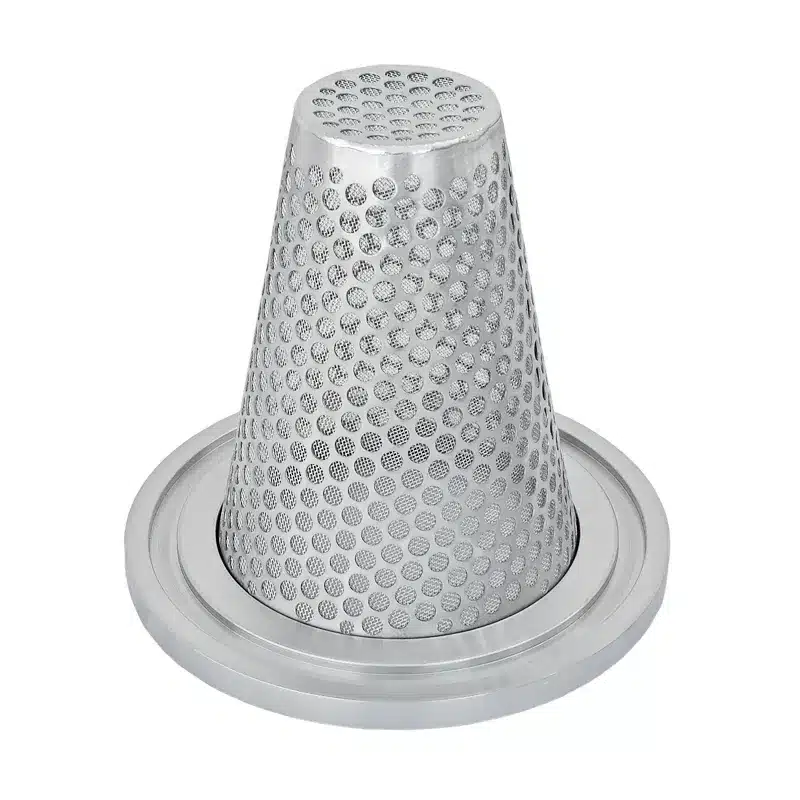
The witch hat strainer is a conical screen in stainless steel, made of perforated plate and wire mesh. It is clamped between two standard flanges as a wafer-type strainer; in plant engineering it is often also called a cone strainer. The witch hat strainer requires no modification to the pipeline and is installed within an hour – and removed just as quickly when needed.
The conical shape, often simply called the cone on site, is the whole trick: it accommodates a multiple of the screen area of a flat disc without lengthening the line. That is why a witch hat strainer lasts longer than any other wafer-type strainer.
The design
A flat screen has at most the area of the pipe cross-section. A cone projecting into the line has several times that. Four things follow from this.
The lateral surface of the cone is considerably larger than the pipe cross-section. The flow is distributed instead of building up against a disc.
Because the area is larger, the flow velocity through the mesh is lower. The pressure loss stays low, even with a fine mesh.
A cone takes up more dirt before it clogs. Where a flat screen has to be changed after hours, the witch hat strainer lasts through the start-up phase.
With flow from the inside, everything collects in the cone. When pulled, the strainer comes out together with its contents instead of emptying into the line.
Screen and perforated plate
The standard is 1 mm. Below and above that, 0.1 · 0.25 · 0.5 · 0.8 · 1.2 and 2 mm are available. For special cases we manufacture elements from 0.05 to 10 mm.
For the start-up phase it may be fine – the strainer is supposed to clog and is pulled afterwards. If it stays in the line permanently, the right mesh size is the coarsest one that still prevents damage.
The wire mesh alone would not withstand the differential pressure. It therefore lies on a perforated plate whose perforation increases with the nominal size:
The material thickness of the screen ring is 3 mm up to DN150 and 5 mm above. A reinforced design is available for high differential pressure.
Designs
The installation position is free: horizontal or vertical. What is not free is the flow direction – that belongs in the order.
Four examples show how we adapt the witch hat strainer to your plant. We are happy to agree further shapes with you.
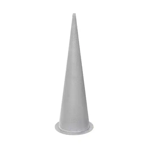
The cone runs out into a point without a top surface. The entire lateral surface is thus screen area, and the dirt collects at one point.
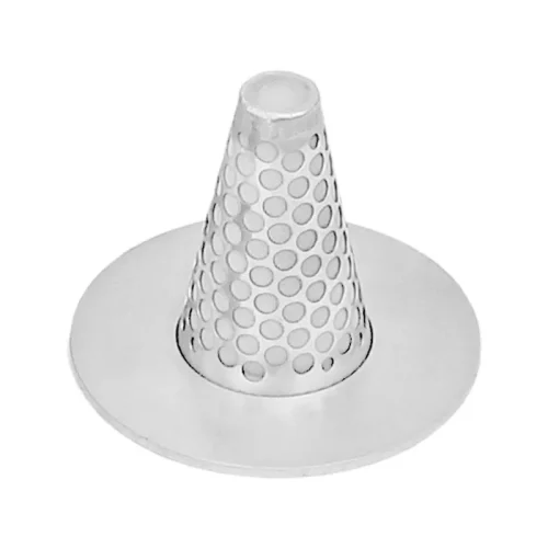
We enlarge the outside diameter of the screen ring beyond the dimension table. This helps with flanges to other standards and with gaskets with a larger contact area.
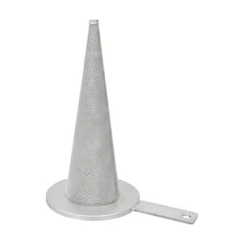
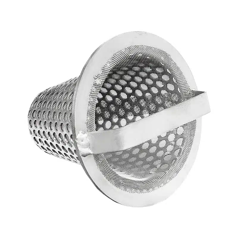
The handle protrudes between the flanges. It shows from the outside that a strainer is installed and serves as a grip when pulling it out. Its length depends on your plant.
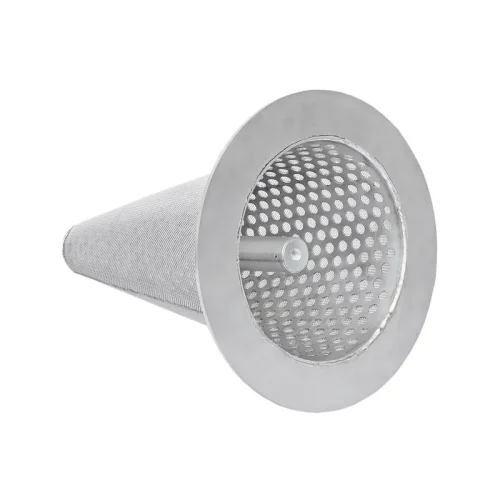
A magnetic cylinder in the cone retains rust, scale and other ferromagnetic particles. It also catches particles that are finer than the mesh size. More on this under Magnetic strainers and magnetic rods.
Sealing face
The witch hat strainer hangs with its screen ring between two flanges, and the cone projects into the line. The ring must therefore match the sealing face of the flanges. As standard, the ring is flat. For flanges with a groove or tongue to DIN EN 1092-1, we manufacture it in the mating form. If the flange has a tongue, the ring receives a groove on that side – and vice versa.
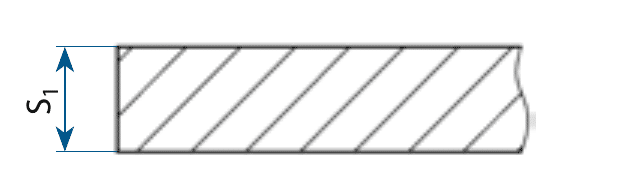
Flat · Standard
The screen ring is flat on both sides. It fits flanges with a flat face or a raised face.
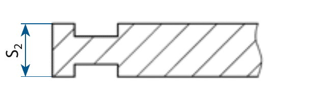
Groove – groove
A groove on both sides. The ring sits between two flanges with a tongue.

Groove – tongue
A groove on one side, a tongue on the other. This is the form for the usual tongue and groove joint made up of one tongue flange and one groove flange.

Tongue – tongue
A tongue on both sides. The ring sits between two flanges with a groove.
The drawings show the cross-section at the sealing face.
With tongue and groove, the screen ring is centred in the joint. The cone thus sits centrally in the pipe and the flow reaches it evenly.
For removal and installation, the flanges have to be spread slightly further apart until tongue and groove are clear. We state the dimensions of the tongue and groove design in our quotation.
Tell us the sealing faces of your flanges, for example Form C and Form D to DIN EN 1092-1. We then manufacture the witch hat strainer in the matching mating form.
Flow direction
The cone has a preferred direction, and it is specified with the order. It determines where the dirt ends up and how the strainer is built.
Inside to outside
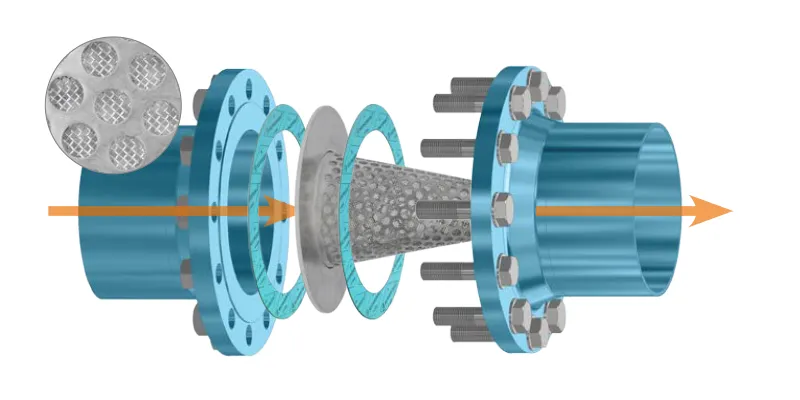
The tip of the cone points against the flow. The medium flows into the cone and outwards through the mesh. The dirt collects inside and comes out with the strainer.
Outside to inside
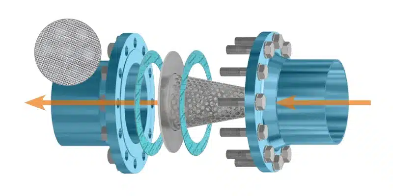
The tip points with the flow. Filtration is from outside to inside, and the dirt settles on the outside. This version is chosen when the line cannot be reversed.
The construction of the mesh follows the direction: it lies on the inside or outside of the perforated plate so that the support body is always on the pressure side. Tell us the flow direction – both depend on it.
Dimensions
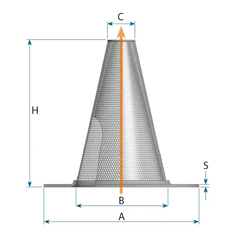
∅ A is the outside diameter of the screen ring, ∅ B the inside diameter. Both depend on the pressure rating, because the ring has to fit the respective flanged joint. ∅ C is the tip of the cone, H the overall height.
| DN | PN10 ∅A/B | PN16 ∅A/B | PN25 ∅A/B | PN40 ∅A/B | Tip ∅C | Height H | Thickness S |
|---|---|---|---|---|---|---|---|
| DN25 | 70/26 | 70/26 | 70/26 | 70/26 | 10 | 40 | 3 |
| DN32 | 81/32 | 81/32 | 81/32 | 81/32 | 13 | 50 | 3 |
| DN40 | 91/40 | 91/40 | 91/40 | 91/40 | 17 | 60 | 3 |
| DN50 | 106/50 | 106/50 | 106/50 | 106/50 | 19 | 80 | 3 |
| DN65 | 126/65 | 126/65 | 126/65 | 126/65 | 26 | 100 | 3 |
| DN80 | 141/80 | 141/80 | 141/80 | 141/80 | 33 | 120 | 3 |
| DN100 | 161/100 | 161/100 | 167/100 | 167/100 | 46 | 140 | 3 |
| DN125 | 191/125 | 191/125 | 193/125 | 193/125 | 59 | 170 | 3 |
| DN150 | 216/150 | 216/150 | 222/150 | 222/150 | 76 | 190 | 3 |
| DN200 | 271/200 | 271/200 | 282/200 | 288/200 | 99 | 260 | 5 |
| DN250 | 326/250 | 327/250 | 338/250 | 350/250 | 126 | 320 | 5 |
| DN300 | 376/300 | 382/300 | 398/300 | 415/300 | 148 | 390 | 5 |
| DN350 | 436/330 | 442/330 | 455/330 | 472/330 | 159 | 440 | 5 |
| DN400 | 487/380 | 493/380 | 512/380 | 544/380 | 186 | 500 | 5 |
| DN450 | 537/430 | 553/430 | 562/430 | 569/430 | 208 | 570 | 5 |
| DN500 | 592/475 | 615/475 | 622/475 | 626/475 | 226 | 640 | 5 |
All dimensions in millimetres. Larger nominal sizes are available on request – we have built witch hat strainers up to DN800. For ANSI flanges to ASME B16.5 we adapt the ring dimensions accordingly.
Enquiry
Nominal size, pressure rating and mesh size are sufficient for a quotation. Add further sizes with “+ further item”. Whatever you leave open, we design to standard.
In the shop
For standard sizes, the shop is the quicker route. You select nominal size, pressure rating and mesh size and add the strainer straight to your shopping basket.
To the witch hat strainer in the shop →
Direct
+49 34956 39960
Monday to Friday, 7 am to 4 pm (CET)
You can reach us by email at info@industriefabrik.com.
Frequently asked questions
At the same nominal size, the witch hat strainer has a multiple of the screen area and therefore clogs later. However, it projects into the line – directly behind a bend or upstream of a valve there is not always room for it. That is where the flat plate strainer fits.
Until the line has been flushed clean, usually a few operating hours to a few days. It can remain as permanent protection – then a differential pressure gauge across it, upstream and downstream, is needed and a coarser mesh size should be selected.
By the rising differential pressure. Without measurement, you only notice it from the falling flow rate – by then the strainer has long been blocked. With permanent installation, measurement is therefore not an accessory but a prerequisite.
Yes, if the flanges are to DIN EN 1092-1 – the screen ring is simply clamped between the sealing faces, the bolts remain the same. For ANSI flanges to ASME B16.5 we make the ring dimensions to suit.
From DN200 the material thickness increases to 5 mm, and the overall height grows considerably – at DN500 the cone projects 640 mm into the line. Check whether a valve or a bend is in the way there.
Yes. The outside diameter of the ring, inside diameter, overall height, cone tip and mesh size are sufficient. A photo of the old part helps to identify the design of the rim.
For a quotation we need nominal size, pressure rating, mesh size and the flow direction. For reproductions, the dimensions of the old part are sufficient. Standard sizes are available directly in the catalogue.