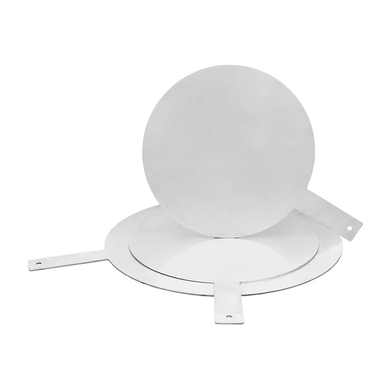
Spade blind · Paddle blind
The spade blind (paddle blind) is a solid line blind without a bore, clamped between two flanges. It isolates the pipeline mechanically – and this can be seen, because the handle projects from between the flanges.
This is exactly its advantage over a closed valve: a valve can leak or be opened by mistake. A spade blind cannot. Unlike a blind flange, which closes off a pipe end, it sits between two flanges. We also supply blind flanges to DIN EN 1092-1, with machined groove, tongue or bore on request.
Application
There are situations in which a closed valve is not enough. Then the spade blind goes into the pipeline.
As long as someone is working on a vessel or apparatus, the supply line must be demonstrably isolated. The visible handle is the proof.
When a section is pressure-tested, the line is blinded off at its boundaries – otherwise the test pressure acts on parts of the plant that are not designed for it.
A line taken out of service stays blinded off until it is needed again. The disc prevents it from being put back into operation by mistake.
While one part of the plant is already running and the next is still being built, the spade blind keeps the two states cleanly apart.
Thickness
A spade blind holds the full operating pressure against a closed surface. What otherwise flows through the pipe presses on a plate here – with the pressure multiplied by the entire cross-sectional area.
That is why the thickness increases considerably with nominal size and pressure rating: at DN50, 10 mm is enough; at DN500 and PN40 this becomes 50 mm. A disc that is too thin risks bending and no longer supporting the gasket.
A spade blind needs a paddle spacer. When the line is released again, the flanged joint has to keep its dimension – that is what the ring is for. Paddle spacer (ring spacer)

Material
The spade blind holds back the medium with its entire surface. The longer it stays in the line, the more its resistance matters.
Standard
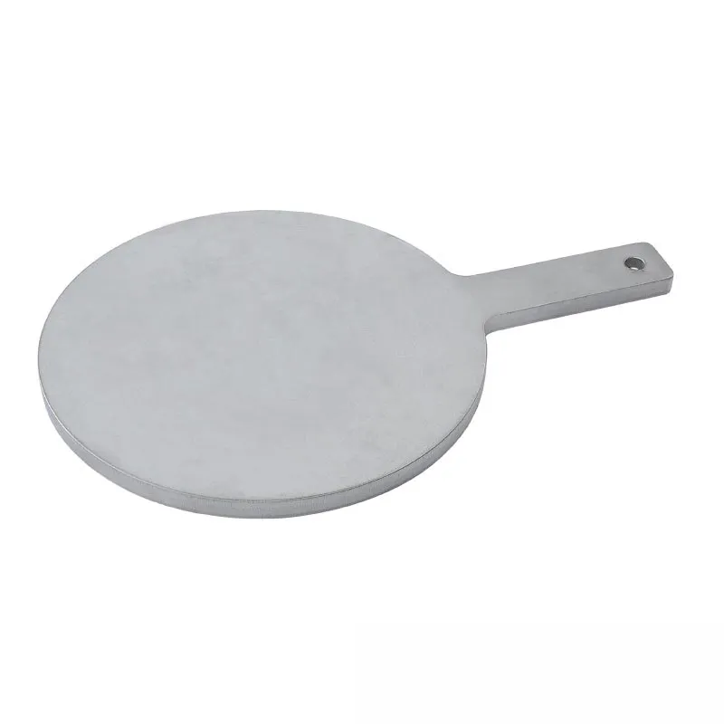
This stainless chromium-nickel steel needs no coating. It stays bright in water, in many aqueous solutions and in humid air. As a result, the disc does not seize in the flange, and the handle remains legible.
Economical alternative
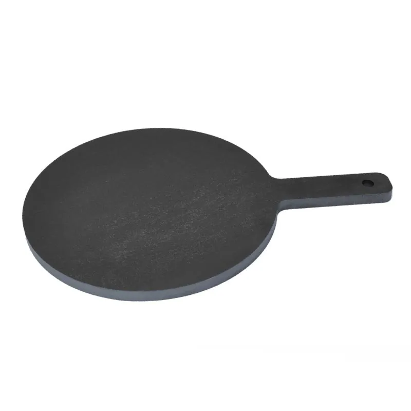
The heat-resistant pressure vessel steel P265GH is designed for pressure and elevated temperatures. It suits lines made of non-alloy steel, as are common for steam, hot water, oil and gas. Where moisture and oxygen come together, it rusts. In dry or oily media this does not matter.
Other materials are available on request, for example 1.4571 for media containing chlorides. Tell us the medium, the temperature and the material of the flanges. We will then recommend the right design.
Design
Venting
Medium often remains trapped between the spade blind and the closed valve. Sometimes there is still pressure there, too. A vent on the disc releases both in a controlled way before anyone loosens the bolts.
Standard
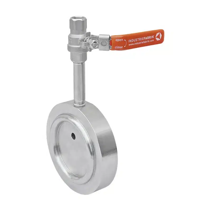
The ball valve sits on the outside of the disc. A bore connects it to the isolated section of the line. During filling, air escapes through it. Before opening, the section can be depressurised and drained.
With pressure indication
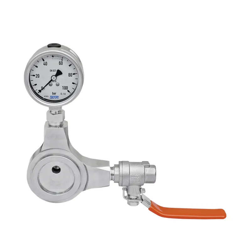
In addition, a pressure gauge shows the pressure behind the disc. This lets the installation team see before opening that the section is depressurised. During the pressure test, you read the test pressure directly at the isolation point.
The ball valve is the standard, but not the only option. Whether flange connection, weld connection, female thread or male thread: we fit the spade blind with the connection type that suits your line. We supply the accessories to your specification.
We match connection, measuring range and material to the medium and pressure rating. Please tell us the test pressure. Also let us know whether the disc stays in the line permanently.
Sealing face
A line blind has to match the sealing face of the flanges between which it sits. As standard, it is flat on both sides. For flanges with groove or tongue to DIN EN 1092-1, we manufacture the mating form. If the flange has a tongue, the disc is given a groove on that side – and vice versa.
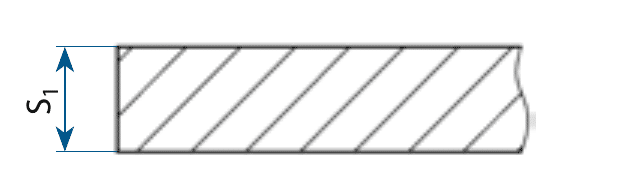
Flat · Standard
Flat and unmachined on both sides, optionally with raised face Form BB. Suits flanges with a flat sealing face or a raised face.
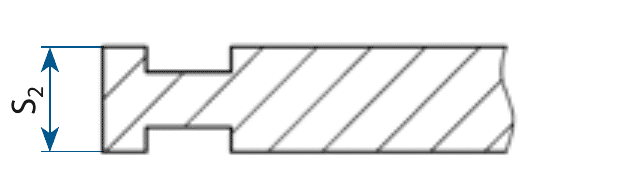
Groove – groove
A groove on both sides. The disc sits between two flanges with tongue.

Groove – tongue
A groove on one side, a tongue on the other. This is the form for the usual tongue and groove joint made up of one tongue flange and one groove flange.

Tongue – tongue
A tongue on both sides. The disc sits between two flanges with groove.
On the spade blind, the tongue and groove joint carries the full pressure on the closed surface. The gasket stays in its chamber even when the line is pressure-tested.
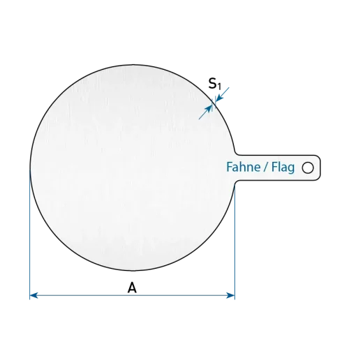
The dimension table gives the thickness S1 of the flat design. With groove or tongue, we determine the thickness separately and state it in the quotation.
Tell us the sealing faces of your flanges, for example Form C and Form D to DIN EN 1092-1. We will then supply the matching mating form.
Dimensions
∅ A is the outside diameter, S the thickness of the disc – both per pressure rating. All dimensions in millimetres.
| DN | PN6 ∅A/S | PN10 ∅A/S | PN16 ∅A/S | PN25 ∅A/S | PN40 ∅A/S |
|---|---|---|---|---|---|
| DN10 | 39 / 4 | 46 / 6 | 46 / 6 | 46 / 6 | 46 / 6 |
| DN15 | 44 / 4 | 51 / 6 | 51 / 6 | 51 / 6 | 51 / 6 |
| DN20 | 54 / 4 | 61 / 6 | 61 / 6 | 61 / 6 | 61 / 6 |
| DN25 | 64 / 4 | 71 / 6 | 71 / 6 | 71 / 6 | 71 / 6 |
| DN32 | 76 / 4 | 82 / 8 | 82 / 8 | 82 / 8 | 82 / 8 |
| DN40 | 86 / 4 | 92 / 8 | 92 / 8 | 92 / 8 | 92 / 8 |
| DN50 | 96 / 6 | 107 / 10 | 107 / 10 | 107 / 10 | 107 / 10 |
| DN65 | 116 / 6 | 127 / 10 | 127 / 10 | 127 / 10 | 127 / 10 |
| DN80 | 132 / 6 | 142 / 12 | 142 / 12 | 142 / 12 | 142 / 12 |
| DN100 | 152 / 6 | 162 / 10 | 162 / 10 | 168 / 15 | 168 / 15 |
| DN125 | 182 / 8 | 192 / 10 | 192 / 10 | 194 / 15 | 194 / 15 |
| DN150 | 207 / 8 | 218 / 12 | 218 / 12 | 224 / 20 | 224 / 20 |
| DN200 | 262 / 10 | 273 / 12 | 273 / 15 | 284 / 20 | 290 / 25 |
| DN250 | 317 / 12 | 328 / 15 | 329 / 20 | 340 / 25 | 352 / 30 |
| DN300 | 373 / 12 | 378 / 20 | 384 / 20 | 400 / 25 | 417 / 35 |
| DN350 | 423 / 15 | 438 / 20 | 444 / 25 | 457 / 30 | 474 / 35 |
| DN400 | 473 / 20 | 489 / 20 | 495 / 25 | 514 / 30 | 546 / 40 |
| DN450 | 528 / 20 | 539 / 25 | 555 / 30 | 564 / 35 | 571 / 45 |
| DN500 | 578 / 20 | 594 / 25 | 617 / 30 | 624 / 40 | 628 / 50 |
Higher pressure ratings up to PN160 and larger nominal sizes are available on request, as are sealing faces of Forms B, C and D.
Enquiry
For a quotation we need nominal size, pressure rating and material. If the test pressure is above the nominal pressure rating, please state it as well – the thickness depends on it. Add further sizes with “+ further item”.
In the shop
For standard sizes, the shop is the quicker route. You select nominal size, pressure rating and material and add the disc directly to your basket.
To the spade blind in the shop →
Direct
+49 34956 39960
Monday to Friday, 7 am to 4 pm (CET)
You can reach us by email at info@industriefabrik.com.
Frequently asked questions
Because a closed valve cannot be proven to be tight and can be opened. For work on a plant section, safety regulations require a mechanical isolation that is recognisable from the outside – that is what the spade blind with its handle provides.
Yes, if the line is open in normal operation. Otherwise the thickness of the spade blind is missing from the flanged joint when it is removed. If you need both states frequently, choose the spectacle blind straight away.
This is given in the dimension table to DIN 2626 – graded by nominal size and pressure rating. For test pressures above the nominal pressure rating, we design the thickness to the actual pressure.
That depends on the medium and on whether the disc stays in the line permanently. Stainless steel 1.4301 is the standard, carbon steel 1.0425 (P265GH) the lower-cost choice for non-critical media.
For a quotation we need nominal size, pressure rating and material. If the test pressure is above the nominal pressure rating, please state it as well – the thickness depends on it. Standard sizes are available directly in the catalogue.