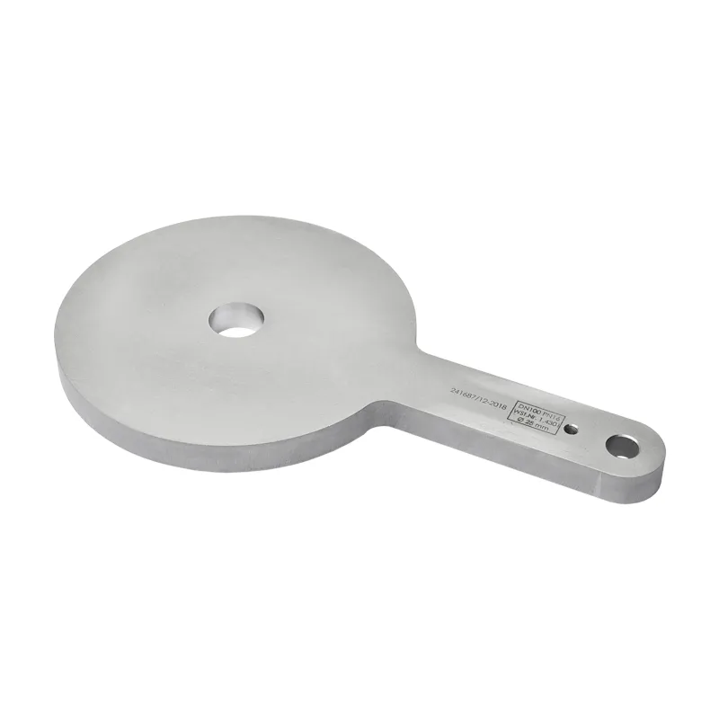
Restriction orifice plate · Restriction orifice
The restriction orifice plate is a plate with a reduced bore, clamped between two flanges. As a restriction orifice or flow restrictor in the pipeline, it limits the flow rate and reduces pressure in a defined way – without moving parts, without maintenance, without auxiliary power.
Where a pump delivers too much or the upstream pressure is too high, the restriction orifice plate in the pipeline is the simplest solution: one component with a fixed bore diameter. As a manufacturer, we make restriction orifices and paddle-type restriction orifice plates to your design data.

Distinction
The two are regularly confused because both have a bore. The difference is fundamental.
Reduced bore. It is meant to limit the flow and reduce pressure. The diameter follows the calculation, not the nominal size.
Full bore. It only keeps the space of the removed spade blind free and changes nothing in the flow. To the paddle spacer →
The name restriction orifice is also common and refers to the same component.
Design
Everything on the restriction orifice plate is standardised – except the bore. It is application-specific and is calculated for each case. We need four details for this.
Density and viscosity determine how much flows through a given bore. Water behaves differently from oil, gas differently from both.
What is to flow through – and what may flow through at most. The difference determines how much throttling is needed.
What is present upstream of the plate. Together with the required pressure downstream, this gives the difference to be reduced.
It affects the fluid properties and therefore the result – and helps determine which material is suitable.
With these four details we design the bore diameter. If one is missing, we do not guess – an incorrectly calculated orifice either throttles too little or causes cavitation.
Design
Material
At the bore the medium flows faster than in the pipe. Rust on the bore edge changes the cross-section and therefore the flow rate for which the plate is designed.
For aqueous media, stainless steel is therefore the safe choice. In oil, steam or gas, carbon steel works just as reliably.
Standard
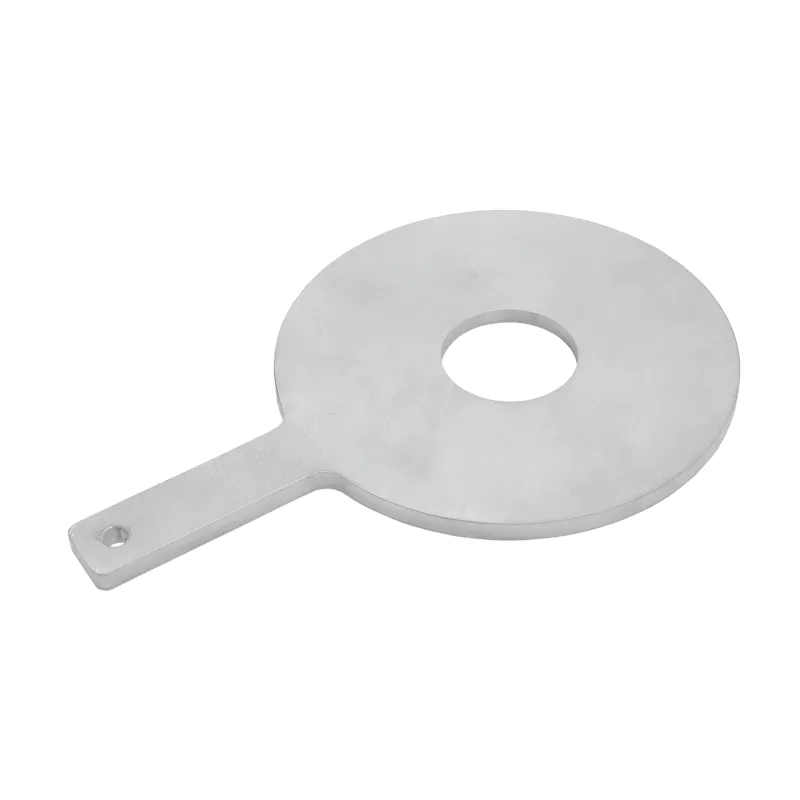
This stainless chromium-nickel steel needs no coating. It stays bright in water, in many aqueous solutions and in humid air. The plate therefore does not seize in the flange, and the handle remains legible.
Economical alternative
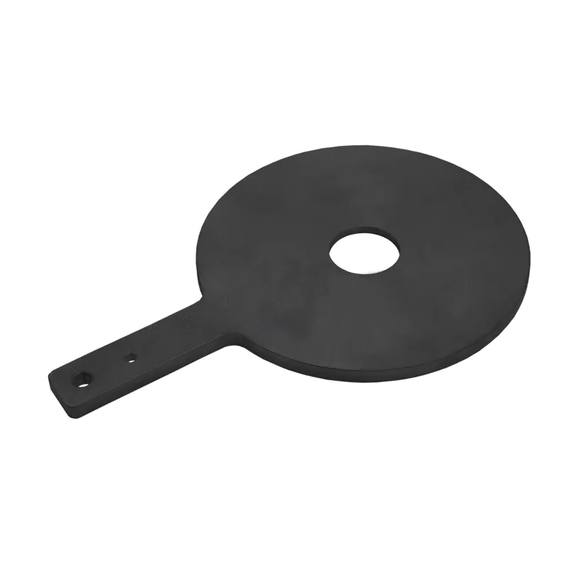
The heat-resistant pressure vessel steel P265GH is designed for pressure and elevated temperature. It suits lines in unalloyed steel, as are usual for steam, hot water, oil and gas. Where moisture and oxygen come together, it rusts. In dry or oily media this does not matter.
Other materials are available on request, for example 1.4571 for media containing chlorides. Tell us the medium, the temperature and the material of the flanges. We will then recommend the right design.
Vent
Before work on the line, pressure is often still present at a restriction orifice plate too. For this, the restriction orifice plate with vent has a connection on the side of the ring. Like any restriction orifice plate, it is fitted between two existing flanges. The line does not have to be cut or welded for this.
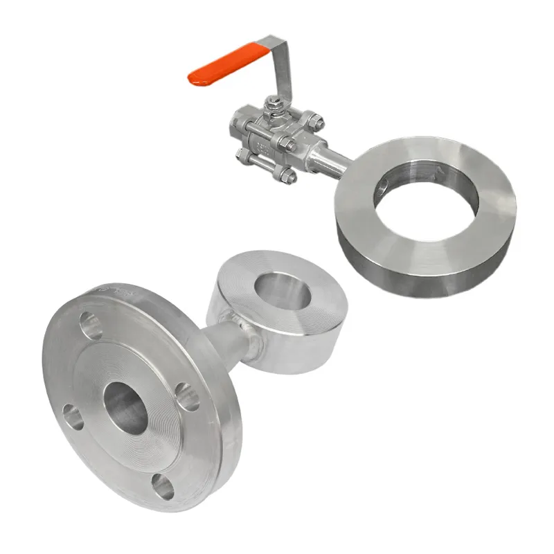
Standard
The ball valve sits on the outside of the ring of the restriction orifice plate. A bore connects it to the flow passage. Before the flanged joint is opened, you depressurise and drain the section through it. When filling, the air escapes.
With flange connection
Instead of the ball valve, the ring has a flanged nozzle. You connect your own valve, a drain line or a pressure gauge to it. Together with a measuring point upstream of the plate, you can see how much pressure the bore reduces.
The connection on the ring depends on your plant. Whether flange connection, weld connection, female thread or male thread: we fit the connection type that suits your line. We supply the accessories to your specification.
Tell us nominal size, pressure rating, medium and the required pressure drop. Also tell us which connection type and which accessories you need. If the restriction orifice plate itself is to remain unchanged, we fit a paddle spacer with vent directly next to it.
Sealing face
A line blind must match the sealing face of the flanges between which it sits. As standard it is flat on both sides. For flanges with tongue or groove to DIN EN 1092-1 we make the mating form. If the flange has a tongue, the plate has a groove on that side – and vice versa.
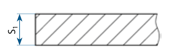
Flat · Standard
Flat and unmachined on both sides, optionally with raised face Form BB. Suits flanges with a flat sealing face or a raised face.
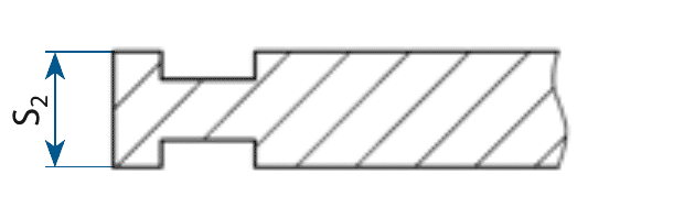
Groove – groove
A groove on both sides. The plate sits between two flanges with a tongue.

Groove – tongue
One side with a groove, the other with a tongue. This is the form for the usual tongue and groove joint between a tongue flange and a groove flange.

Tongue – tongue
A tongue on both sides. The plate sits between two flanges with a groove.
Tongue and groove are located in the sealing area of the plate. We design the orifice bore independently of this, to your operating point.
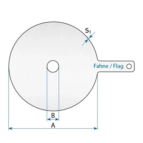
The dimension table gives the thickness S1 of the flat design. With tongue or groove we determine the thickness separately and state it in our quotation.

Tell us the sealing faces of your flanges, for example Form C and Form D to DIN EN 1092-1. We will then supply the matching mating form.
Dimensions
∅ A is the outside diameter, S the thickness. The bore diameter is not given in the table – it follows the design. All dimensions in millimetres.
| DN | Bore ∅B | PN6 ∅A/S | PN10 ∅A/S | PN16 ∅A/S | PN25 ∅A/S | PN40 ∅A/S |
|---|---|---|---|---|---|---|
| DN10 | to design | 39 / 4 | 46 / 6 | 46 / 6 | 46 / 6 | 46 / 6 |
| DN15 | to design | 44 / 4 | 51 / 6 | 51 / 6 | 51 / 6 | 51 / 6 |
| DN20 | to design | 54 / 4 | 61 / 6 | 61 / 6 | 61 / 6 | 61 / 6 |
| DN25 | to design | 64 / 4 | 71 / 8 | 71 / 8 | 71 / 8 | 71 / 8 |
| DN32 | to design | 76 / 4 | 82 / 8 | 82 / 8 | 82 / 8 | 82 / 8 |
| DN40 | to design | 86 / 4 | 92 / 8 | 92 / 8 | 92 / 8 | 92 / 8 |
| DN50 | to design | 96 / 6 | 107 / 10 | 107 / 10 | 107 / 10 | 107 / 10 |
| DN65 | to design | 116 / 6 | 127 / 12 | 127 / 12 | 127 / 12 | 127 / 12 |
| DN80 | to design | 132 / 6 | 142 / 12 | 142 / 12 | 142 / 12 | 142 / 12 |
| DN100 | to design | 152 / 6 | 162 / 10 | 162 / 10 | 168 / 15 | 168 / 15 |
| DN125 | to design | 182 / 8 | 192 / 12 | 192 / 12 | 194 / 20 | 194 / 20 |
| DN150 | to design | 207 / 8 | 218 / 15 | 218 / 15 | 224 / 20 | 224 / 20 |
| DN200 | to design | 262 / 10 | 273 / 15 | 273 / 20 | 284 / 20 | 290 / 25 |
| DN250 | to design | 317 / 12 | 328 / 15 | 329 / 20 | 340 / 25 | 352 / 30 |
| DN300 | to design | 373 / 12 | 378 / 20 | 384 / 25 | 400 / 30 | 417 / 35 |
| DN350 | to design | 423 / 15 | 438 / 20 | 444 / 25 | 457 / 35 | 474 / 40 |
| DN400 | to design | 473 / 20 | 489 / 25 | 495 / 30 | 514 / 35 | 546 / 45 |
| DN450 | to design | 528 / 20 | 539 / 25 | 555 / 35 | 564 / 40 | 571 / 50 |
| DN500 | to design | 578 / 20 | 594 / 30 | 617 / 35 | 624 / 45 | 628 / 55 |
For larger nominal sizes the restriction orifice plate is thicker than the other line blinds, because the reduced bore takes a higher pressure difference. Higher pressure ratings up to PN160 and larger nominal sizes on request.
Enquiry
We design the bore for your operating point. For this we need four details besides nominal size and pressure rating: medium, flow rate, upstream pressure and operating temperature. If you know the pressure downstream of the plate, include it as well. Add further sizes with “+ further item”.
Direct
+49 34956 39960
Monday to Friday, 7 am to 4 pm (CET)
You can reach us by email at info@industriefabrik.com.
Frequently asked questions
The medium with density and viscosity, the required flow rate, the upstream pressure and the pressure required downstream, and the operating temperature. These values give the bore diameter.
The plate throttles to a fixed value – without actuator, without maintenance, without risk of failure. A control valve is the choice when operating conditions change and readjustment is needed.
Then cavitation can occur at the bore – this damages the component and causes noise. In such cases the throttling is spread over several stages. The design shows whether this is necessary.
No. Both reduce the cross-section, but the flow measuring orifice is built for measuring and follows other standards for inlet straight lengths and edge geometry. The restriction orifice plate is meant to throttle, not to measure.
Boring out is possible, reducing is not. If the operating data are not yet fixed, it makes more sense to design smaller at first and enlarge the bore if necessary.
Tell us the medium, flow rate, upstream pressure, required downstream pressure and the operating temperature. From this we calculate the bore diameter and recommend the right design.